Introduction
The Arduino Pro Micro is a versatile microcontroller board that offers a compact size and powerful capabilities. Understanding Pro Micro Pinout and schematic details is crucial for successful project development. In this comprehensive guide, we will delve into the pin configuration of the board, explaining the usage and functionality of each pin in simple English. This information will help you navigate the board effectively and unlock its full potential.
Arduino Pro Micro is a microcontroller board based on the ATmega32U4 microcontroller. The board dimensions are approximately 34.29mm x 25.4mm (1.35″ x 1.0″).
Before we dive further into the topic, please make sure that you have read the Arduino Pro Micro for Beginners blog post and Understanding Microcontroller Terms blog post as you will be encountering many of the terms along the article and it’s recommended that you familiarise yourself with basic knowledge and the terms.
Pro Micro Pinout Overview
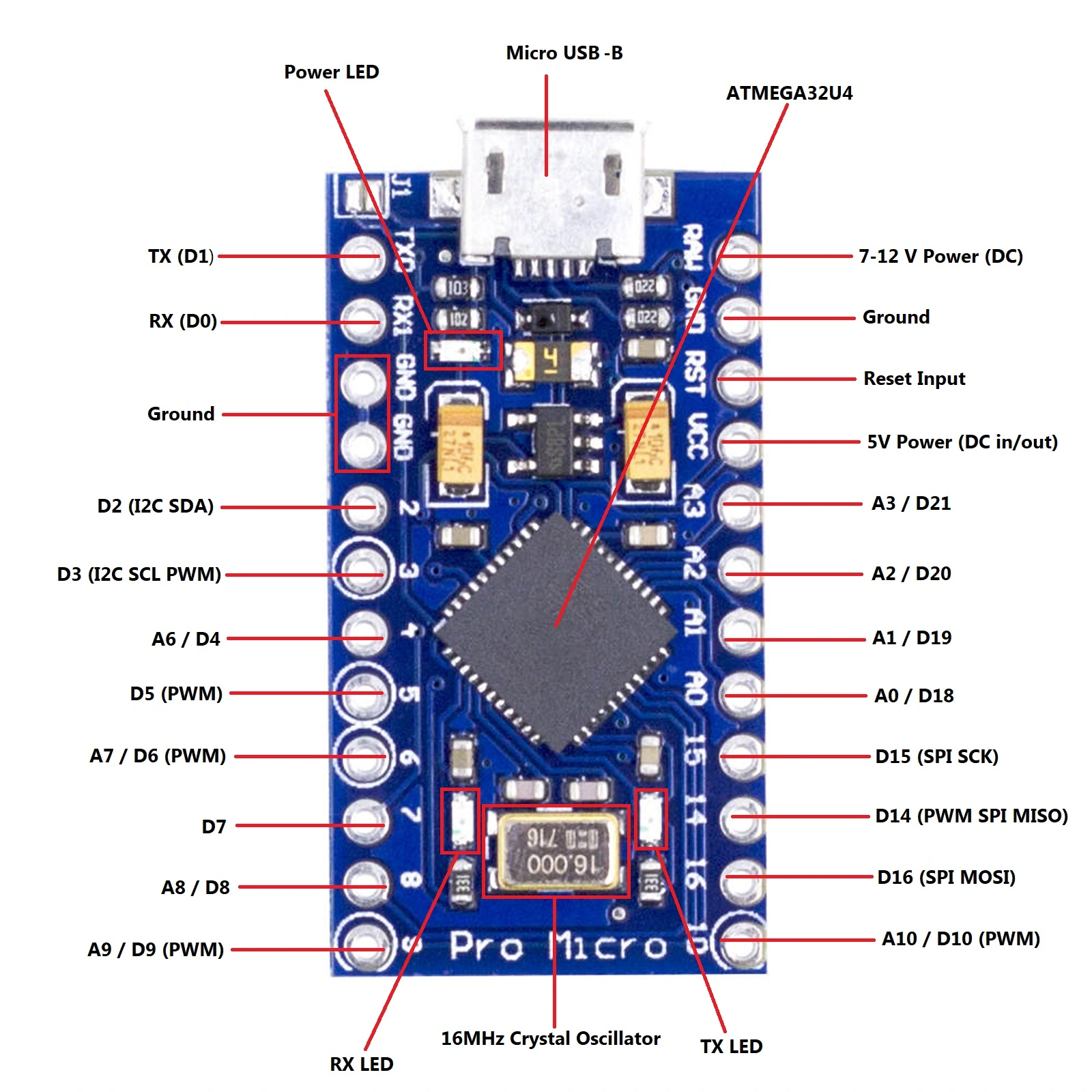
The Pinout features a total of 18 digital input/output pins, 8 analog pins, and several specialized pins for specific functions. Let’s explore each pin details and their functionalities:
Digital Pins (D0-D10, D14-D16, D18-D21)
- All digital pins, labeled D0-D10, D14-D16 and D18-D21 as per the above diagram, can be configured as either input or output.
- They can be utilized for tasks such as controlling LEDs, reading digital sensors, or interfacing with other digital devices.
Analog Pins (A0-A3, A6-A10)
- The board provides 9 analog input pins, labeled A0-A3 and A6-A10 as per the above diagram.
- These pins are primarily used for reading analog signals from sensors or potentiometers.
- They can also function as digital pins if needed.
PWM Pins
- Six of the digital pins (D3, D5, D6, D9, D10, D14) on the board are capable of generating Pulse Width Modulation (PWM) signals.
- PWM allows for creating analog-like output, useful for applications like controlling motor speed or LED brightness.
- Specialized Pins:
- RST (Reset Pin): This pin is used to restart the board and initiate a reset.
- GND (Ground Pin): It provides the common reference voltage (0V) for the system.
- RAW: The unregulated voltage input for the board. It can accept voltages up to 12V when powering the board externally.
- VCC: It supplies the regulated voltage to the on-board ATmega32U4. The voltage depends on the board’s version (3.3V/8MHz or 5V/16MHz).
I/O Capabilities
- The board’s digital pins can be configured as either INPUT or OUTPUT.
- They support standard logic levels (0V and 5V) and can handle signals within this voltage range.
- The analog pins (A6-A10) can function as digital pins by using their corresponding digital pin numbers.
Understanding the Power in Arduino Pro Micro Pinout
One significant aspect of the Arduino Pro Micro, adding to its versatility and usability, is its array of pinouts. These Arduino Pro Micro pinouts are more than just mere connection points; they are the powerful gateways for communication between the controller and the outside world.
The Arduino Pro Micro comes equipped with an extensive array of pinouts – 18 digital input/output pins, 6 PWM channels, and 9 analog inputs. Each pin has its own specialty and usage, which contributes to the variety of applications that the microcontroller can handle. Whether you’re interfacing with sensors in an IoT project, controlling servos in robotics, or sending MIDI signals in a music project, mastering these Arduino Pro Micro pinouts is crucial.
Arduino Pro Micro Power Supply
The board operates at a voltage of 5V and can be powered via the USB connection or an external power supply. It also has a built-in USB connection for programming and communication with a computer.
Some variations of the board, such as those with a built-in voltage regulator, can handle higher voltages such as 12V when provided through the RAW pin or the VIN pin. These boards have a voltage regulator that can step down the input voltage to the required 5V for proper operation.
However, it is important to note that the specific capabilities and features of different variants of the board may vary. It is always recommended to refer to the manufacturer’s specifications or documentation for the specific board you are using to confirm its voltage compatibility.
If your board does not have a voltage regulator or clear documentation, it is safest to assume it is designed for a maximum input voltage of 5V. In that case, you should use a separate voltage regulator to step down the 12V supply to 5V before connecting it to the board to prevent any potential damage.
Schematic Details and Advanced Functionality
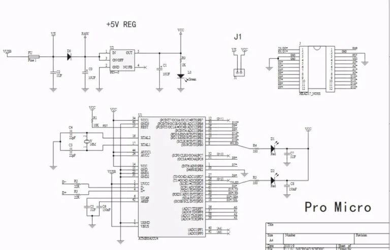
To fully understand the inner workings of this development board, studying the Arduino Pro Micro schematicdiagram is beneficial. The schematic illustrates the electrical connections between components, enabling more advanced experimentation and troubleshooting possibilities.
Conclusion
Understanding the Pro Micro pinout and schematic details is crucial for effectively utilizing its capabilities. By mastering the functionality of each pin, you can unlock the full potential of the board and create exciting projects. Whether you are a beginner or an experienced maker, this comprehensive guide serves as an invaluable resource to help you navigate and maximize the possibilities in your projects.