
Home automation is changing the way we interact with our homes. Using a affordable microcontroller such as an Arduino Uno, you can create a smart lighting system which improves safety and convenience in and around the house.
Today we are going to show you how to do two different home automation projects. The first project I’m going to go over is how to make some LED Stair Lights that turn on and off while you walk up and down the stairs (Cascading LED Stair Lights). The second project we will go over is how to make an Infrared Sensor Lightsthat turn on based on the ambient light conditions.
Each project will come with a comprehensive list of required components, step-by-step instructions, and sample code to help you get started. Every required components mentioned in this article will be fairly affordable to source online and can also be purchased from us.
Table of Content
1. Introduction to Home Automation
Home automation helps you control different systems in your home remotely or automatically. Using the Arduino, you can create your own home automation system. One of the easiest and useful applications of home automation is smart lighting, as it is not only easy to implement but also saves electricity, since all the lights are turned on and off for your convenience as the room occupancy changes.
2. Project 1: Cascading LED Stair Lights
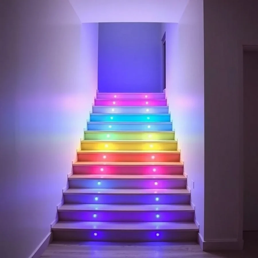
Cascading LED Stair Lights is a fantastic and practical project to play with. It is also really nice to have lights automatically illuminate your stairs so you can see where you’re going. In particular, it becomes handy if you have kids who wake up during the night and walk around the house. This project uses an Arduino Uno to control a series of LEDs that illuminate one by one as soon as you walk towards the stairs as a cascading effect.
Components Required
- Arduino Uno: The main controller.
- LEDs: 5-10 bright white or colored LEDs.
- Resistors: 220-ohm resistors for each LED.
- Breadboard: For easy circuit connections.
- Jumper Wires: For making connections.
- PIR Motion Sensor: To detect movement.
- Power Supply: USB or battery pack for Arduino.
Circuit Diagram of Cascading LED Stair Lights
Here’s the basic circuit diagram for connecting the LEDs and PIR sensor to the Arduino Uno:
       +5V  ───────────────────────────────────────────┐
│
+---+---+
|       |
[LED1]  [LED2]
|       |
+---+---+
│
Resistor
│
└───────── Arduino Pin 2 (for LED1)
│
+5V  ───────────────────────────────────────────┐
│
+---+---+
|       |
[LED3]  [LED4]
|       |
+---+---+
│
Resistor
│
└───────── Arduino Pin 3 (for LED3)
│
+5V  ───────────────────────────────────────────┐
│
+---+---+
|       |
[LED5]  [LED6]
|       |
+---+---+
│
Resistor
│
└───────── Arduino Pin 4 (for LED5)
│
┌───────── PIR Sensor OUT ─────── Arduino Pin 7
│
GND ────────────────────────────── GND
Code Required
Here’s a simple code snippet to control the cascading LED lights based on motion detected by the PIR sensor:
Version 1
#define LED1 2
#define LED2 3
#define LED3 4
#define PIR_SENSOR 7
void setup() {
pinMode(LED1, OUTPUT);
pinMode(LED2, OUTPUT);
pinMode(LED3, OUTPUT);
pinMode(PIR_SENSOR, INPUT);
}
void loop() {
int pirValue = digitalRead(PIR_SENSOR);
if (pirValue == HIGH) {
digitalWrite(LED1, HIGH);
delay(500);
digitalWrite(LED2, HIGH);
delay(500);
digitalWrite(LED3, HIGH);
delay(500);
// Turn off LEDs after a delay
delay(2000);
digitalWrite(LED1, LOW);
digitalWrite(LED2, LOW);
digitalWrite(LED3, LOW);
}
}
Code Explanation For V1
Loop Function: The loop() function reads the PIR sensor value. If it detects motion (HIGH), it sequentially turns on each LED with a delay of 500 milliseconds between each, then keeps them on for an additional 2 seconds before turning them off.
Pin Definitions: You need to correctly define the pins for the LEDs and the PIR sensor.
Setup: The setup() function correctly sets the LED pins as outputs and the PIR sensor pin as input.
Version 2
#define LED1 2
#define LED2 3
#define LED3 4
#define PIR_SENSOR 7
unsigned long previousMillis = 0;
const long interval = 500;  // interval at which to light up LEDs (milliseconds)
int ledState = 0;
void setup() {
pinMode(LED1, OUTPUT);
pinMode(LED2, OUTPUT);
pinMode(LED3, OUTPUT);
pinMode(PIR_SENSOR, INPUT);
}
void loop() {
int pirValue = digitalRead(PIR_SENSOR);
if (pirValue == HIGH) {
unsigned long currentMillis = millis();
// Check if it's time to change the LED state
if (currentMillis - previousMillis >= interval) {
previousMillis = currentMillis;
// Turn off all LEDs if they are already on
if (ledState < 3) {
digitalWrite(ledState + LED1, HIGH);
ledState++;
} else {
// All LEDs have been lit, turn them off
digitalWrite(LED1, LOW);
digitalWrite(LED2, LOW);
digitalWrite(LED3, LOW);
ledState = 0; // Reset for next trigger
}
}
} else {
// Ensure all LEDs are off when no motion is detected
digitalWrite(LED1, LOW);
digitalWrite(LED2, LOW);
digitalWrite(LED3, LOW);
ledState = 0; // Reset state
}
}
This version allows for more flexibility and responsiveness to changes in the PIR sensor state.
Code Explanation For V2
- Avoid Blocking Code: Using
delay()can block other code from running. Consider using a non-blocking approach withmillis()if you want to add more functionality in the future. - PIR Sensor Behavior: Depending on your PIR sensor, you might want to add some logic to handle multiple triggers or debounce the signal.
You may use any version or try both version and see the difference to learn.
Step-by-Step Guide
- Set Up Your Components: Gather all the required components and set them up on a breadboard.
- Connect the PIR Sensor: Connect the PIR sensor to the Arduino Uno. Connect its OUT pin to pin 7 on the Arduino.
- Connect the LEDs: Connect each LED through a resistor to pins 2, 3, and 4 on the Arduino.
- Upload the Code: Use the Arduino IDE to upload the provided code to your Arduino Uno.
- Test Your Project: Move in front of the PIR sensor and watch as the LEDs light up in sequence.
3. Project 2: Infrared Sensor Like Lights Using Light Dependent Resistor
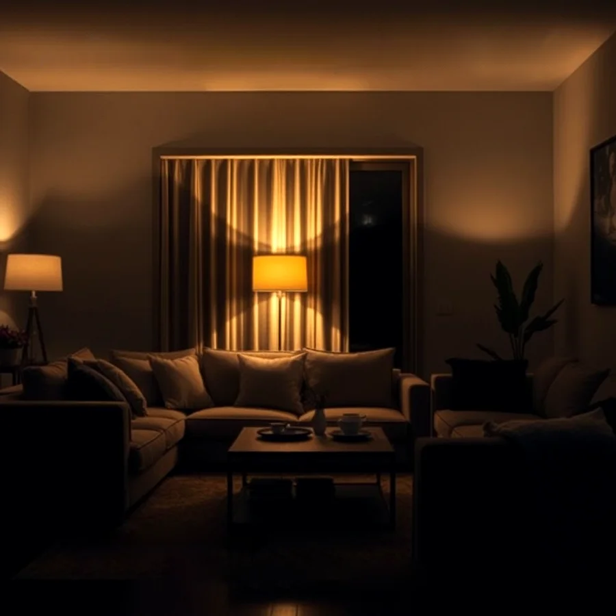
Infrared sensor lights are another excellent home automation project that activates lights based on ambient light conditions. This project uses an LDR (Light Dependent Resistor) to turn on LEDs when it gets dark.
Components Required
- Arduino Uno
- LDR (Light Dependent Resistor)
- Resistor: 10k-ohm resistor for LDR.
- LEDs: Your choice of color.
- Resistors: 220-ohm resistors for LEDs.
- Breadboard
- Jumper Wires
- Power Supply
Circuit Diagram of Infrared Sensor Lights
Here’s how to connect an LDR and LED to the Arduino:
       +5V ───────────────────────────────┐
│
+--------+---------+
|                  |
[LDR]                |
|                  |
+----+----+             |
|         |             |
GND      Resistor         |
(10k)             |
|                |
+----------------+
|
└───────────── Arduino Pin A0 (LDR)
+5V ───────────────────────┐
│
+----+----+
|         |
[LED]     [LED]
|         |
+----+----+
|
Resistor
|
└───────────── Arduino Pin 9 (for LED)
Code Required
This code reads the value from the LDR and turns on the LED when it gets dark:
#define LDR_PIN A0
#define LED_PIN 9
void setup() {
pinMode(LED_PIN, OUTPUT);
}
void loop() {
int ldrValue = analogRead(LDR_PIN);
if (ldrValue < 200) { // Adjust this threshold based on your environment
digitalWrite(LED_PIN, HIGH); // Turn on LED when it's dark
} else {
digitalWrite(LED_PIN, LOW); // Turn off LED when it's bright
}
}
Code Explanation
- Definitions:
#define LDR_PIN A0: This setsLDR_PINto refer to the analogue pin A0 where the LDR is connected.#define LED_PIN 9: This setsLED_PINto refer to digital pin 9 where the LED is connected.
- Setup Function:
void setup(): This function runs once when the Arduino starts.pinMode(LED_PIN, OUTPUT): This configures the specified LED pin as an output pin so it can control the LED.
- Loop Function:
void loop(): This function runs continuously after the setup.int ldrValue = analogRead(LDR_PIN): This reads the analog value from the LDR. The value will be between 0 and 1023, where lower values indicate less light (more darkness).- The
ifstatement checks ifldrValueis less than 200. This is a threshold that you can adjust based on your environment:- If
ldrValue < 200: It means it’s dark enough, so the LED is turned on (digitalWrite(LED_PIN, HIGH)). - Otherwise, if the light level is above that threshold, the LED is turned off (
digitalWrite(LED_PIN, LOW)).
- If
Step-by-Step Guide
- Gather Components: Collect all necessary components for this project.
- Build Your Circuit: Set up your circuit on a breadboard according to the diagram.
- Upload the Code: Open your Arduino IDE and upload the code provided above.
- Test Your Setup: Cover the LDR with your hand or a dark object to simulate darkness and see if the LED lights up.
4. Conclusion
Creating DIY home automation projects like cascading LED stair lights and infrared sensor lights is a rewarding experience that enhances your living space’s safety and convenience. With just a few components and some coding, you can transform your home into a smarter place. These projects not only provide practical solutions but also spark creativity and encourage learning about electronics and programming. Hope this article adds a value to your knowledge.